VHDL tutorial - combining clocked and sequential logic
Quick Links
- Part 1: VHDL tutorial
- Part 2: part 2 - Testbench
- Part 3: combining clocked and sequential logic
- Part 4: Creating a hierarchical design
- Part 5: A practical example - part 1 - Hardware
- Part 6: A practical example - part 2 - VHDL coding
- Part 7: A practical example - part 3 - VHDL testbench
In an earlier article on VHDL programming ("VHDL tutorial" and "VHDL tutorial - part 2 - Testbench", I described a design for providing a programmable clock divider for a ADC sequencer. In this example, I showed how to generate a clock signal (ADCClk), that was to be programmable over a series of fixed rates (20MHz, 10MHz, 4MHz, 2MHz, 1MHz and 400KHz), given a master clock rate of 40MHz. A reader of that article had written to ask if it was possible to extend the design to include a 'pass through' mode, where the 40MHz input clock signal could also be programmed through to the ADC clock output.
The answer is a simple yes. In the prior example, a reloadable, count-down counter (ADC_div) was used to toggle a signal (ADCClk) at the desired rate. This signal was toggled (ADCClk <= not(ADCClk) each time the counter (ADC_div) had been decremented to zero (which would also then be reloaded with its initial value). The internal signal (ADCClk) was later transfered to a specified output port (ADC_CLK) using the following statement.
![]()
To change the output clock assignment, such that it can be either the internal signal (ADCClk), or the input master clock signal (Mclk), we need to change the above statement into a conditional signal assignment. A conditional assignment allows us to select between different signals, based on the state of other signals in the design. By modifying the above statement as follows, when the clock selector (ClkSel) is equal to "000", the ADC clock will be set to the current state of the master clock signal (Mclk), otherwise it will be set to the current state of the internal signal (ADCClk). (It should be noted that signal assignments are not clocked, but are continuously evaluated, allowing the full speed routing of the master clock signal to the specified output.)
![]()
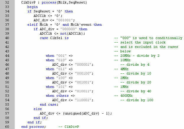
In order to use the "000" setting of the clock selector latch (ClkSel) for the master clock pass through, it is necessary to rearrange the current sections within the ClkSel case statement, as the "000" case was used for the divide by two (20MHz) selection. The modifications to the clock divider logic for these changes are as follows.

With the above changes, the ADC_Clk output of our VHDL design can now be programmed to the following fixed rates (40MHz, 20MHz, 10MHz, 4MHz, 2MHz, 1MHz and 400KHz) by latching the respective values into the clock selector latch (ClkSel = "000", "001", "010", "011", "100", "101" and "110"-"111").
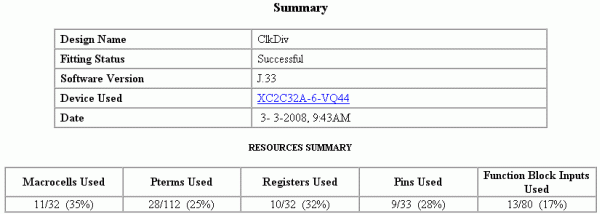
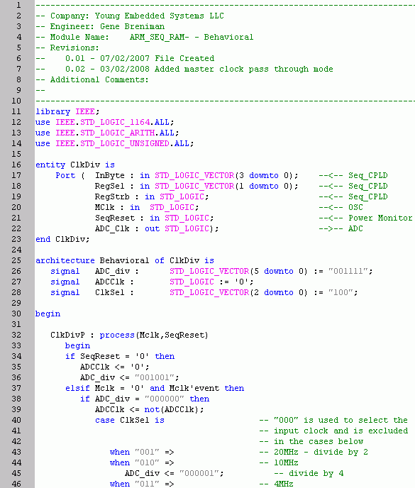
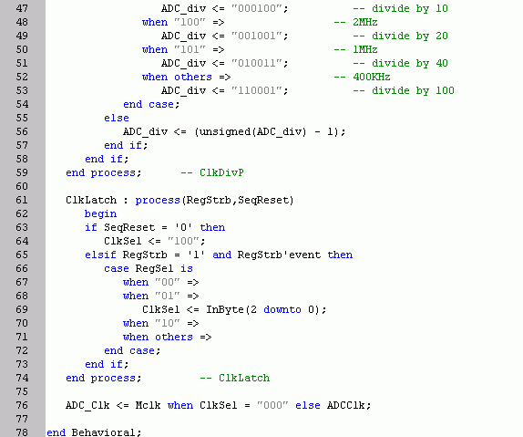
Gathering all the pieces together we get a VHDL program for a Xilinx CPLD that provides the updated programmable clock divider. The modified example, shown at the end of this article, compiled easily into the XC2C32A-6VQ44 part. The summary shows that the part is only partially full, leaving room for still more future enhancements.

Thank you for your comments and suggestions. I look forward to any further questions.
Happy designing!
Gene
--------- Complete modified example -------


- Comments
- Write a Comment Select to add a comment
To post reply to a comment, click on the 'reply' button attached to each comment. To post a new comment (not a reply to a comment) check out the 'Write a Comment' tab at the top of the comments.
Please login (on the right) if you already have an account on this platform.
Otherwise, please use this form to register (free) an join one of the largest online community for Electrical/Embedded/DSP/FPGA/ML engineers:


