


How to use SPI devices in NuttX RTOS
![]()
Quick Links
- Part 1: Getting Started with (Apache) NuttX RTOS - Part 1
- Part 2: Getting Started with (Apache) NuttX RTOS Part 2 - Looking Inside and Creating Your Customized Image
- Part 3: Getting Started with NuttX RTOS on Three Low Cost Boards
- Part 4: Using GPIO in (Apache) NuttX RTOS
- Part 5: Using (Apache) NuttX USERLED Subsystem
- Part 6: Using (Apache) NuttX Buttons Subsystem
- Part 7: How to use I2C devices in (Apache) NuttX: Scanning for Devices
- Part 8: How to use I2C devices in (Apache) NuttX: Adding support for an I2C device in your board
- Part 9: How to use SPI devices in NuttX RTOS
The SPI (Serial Peripheral Interface) is synchronous serial communication protocol (by synchronous it means there is a common clock signal to indicate when which signal transition will occur). Normally SPI is used for short-distance wired communication between chips and it can work at frequencies of tens of MHz or higher.
Compared to I2C, the SPI bus is faster and also full-duplex (it means you can send and receive data at same time). The protocol also is simpler, it is master-slave, meaning that the master will control the clock and how the signal are transmitted and the slave will just react/respond to it.
The protocol normally uses 4 signals/lines to communicate:
- MOSI (Master Out Slave In) - This line is used to send the data from the master to the slave;
- MISO (Master In Slave Out) - This line is used to receive data from the slave;
- SCLK (Serial Clock) - This is the clock line that the master uses to synchronize the signals with the slave;
- SS/CS (Slave Select or Chip Select) - This line is used to indicate to the slave that the master want its attention (selects it to communicate).
There are other details that you need to understand when working with SPI, such as polarity (CPOL) and phase (CPHA) of clock, bit order, etc. But I will assume you have previous experience with SPI and will study a little before trying to use SPI on NuttX. Deal?
Now let explain how SPI is supported on NuttX. It will be focused on RP2040 MCU used on RaspberryPi Pico, but same principle will apply to all other microcontrollers and microprocessors supported by NuttX.
The first thing a NuttX supported microcontroller needs to communicate via SPI is to have hardware support for the internal SPI controller. For RP2040, the internal SPI controller driver is located at nuttx/arch/arm/src/rp2040/rp2040_spi.c. Anyway don't worry about this SPI controller, once it is supported you never will need to touch or modify it.
NB: Actually, even an MCU without SPI controller driver may be able to communicate with some SPI device in NuttX because it has SPI Bitbang driver support. This means there is a driver that can use ordinary GPIOs to emulate an SPI controller. But unless you like "gambiarra" (a Portuguese word for something ugly, usually a workaround for something that should have been done right), please don't use it.
After having support to the SPI controller we also need support to the device we want to use with NuttX. There are many SPI devices supported: Sensors, LCDs, SPI SDCard communication, SPI Ethernet (ENC28J60, W5500, etc), SPI CAN (MCP2525), SPI Audio (VS1053), etc.
Finally we need a glue code on our board to connect the SPI controller to the SPI chip we want to use. This code will define which SPI controller port we want to use (normally each MCU will have two or more SPI controller ports internally), which pins we want to use for SPI (some MCUs let you use different pins configuration to the same port) and also which pins we want to use for Chip Select (CS). An important information here: normally the MCUs have some predefined pins for CS, that normally limited to 4 chip select pins. So in NuttX we bypass this limitation using software defined chip select pins.
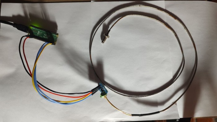
Just like I did for I2C I will show how to add support for a device. I'll add support for a very common MAX6675 thermocouple temperature sensor, showing all the files that need to be added or modified to get it working on NuttX. This way, following the same logic, you could add support to other sensors or even other more advanced device.
So we will create a file glue logic file at boards/arm/rp2040/common/src/rp2040_max6675.c with the code needed to initialize the RP2040 SPI Controller and pass the returned spi dev instance to the max6675_register function:
int board_max6675_initialize(int devno, int busno)
{
  struct spi_dev_s *spi;
  char devpath[12];
  int ret;

  spi = rp2040_spibus_initialize(busno);
  if (spi == NULL)
    {
      syslog(LOG_ERR, "ERROR: Failed to initialize SPI port %d\n", busno);
      return -ENODEV;
    }

  /* Then register the temperature sensor */

  snprintf(devpath, 12, "/dev/temp%d", devno);
  ret = max6675_register(devpath, spi);
  if (ret < 0)
    {
      snerr("ERROR: Error registering MAX6675\n");
    }

  return OK;
}
Note that I didn't created this code from scratch, I used the file boards/arm/stm32/common/src/stm32_max6675.c as reference. This is the good thing about NuttX: there is always some board example that we can use as reference!
Because you added this rp2040_max6675.c file inside boards/arm/rp2040/common/src/ you will need to edit the Make.defs inside this directory and add:
ifeq ($(CONFIG_SENSORS_MAX6675),y)
  CSRCS += rp2040_max6675.c
endif
We also need to create a header file at boards/arm/rp2040/common/include/rp2040_max6675.h with this function prototype to let our board to know that is exists:
/****************************************************************************
 * Name: board_max6675_initialize
 *
 * Description:
 *   Initialize and register the MAX6675 Temperature Sensor driver.
 *
 * Input Parameters:
 *   devno - The device number, used to build the device path as /dev/tempN
 *   busno - The SPI bus number
 *
 * Returned Value:
 *   Zero (OK) on success; a negated errno value on failure.
 *
 ****************************************************************************/

int board_max6675_initialize(int devno, int busno);
Now edit the bring-up file boards/arm/rp2040/common/src/rp2040_common_bringup.c adding this header files:
#ifdef CONFIG_SENSORS_MAX6675
#include <nuttx/sensors/max6675.h>
#include "rp2040_max6675.h"
#endif
And the I2C initialization call for our MAX6675 device inside rp2040_common_bringup() :
#ifdef CONFIG_SENSORS_MAX6675
  /* Try to register MAX6675 device as /dev/temp0 at SPI0 */

  ret = board_max6675_initialize(0, 0);
  if (ret < 0)
    {
      syslog(LOG_ERR, "Failed to initialize MAX6675 driver: %d\n", ret);
    }
#endif
These are all the necessary modifications to get MAX6675 called in your board bring-up process.You need to wire the MAX6675 sensor to your RaspberryPi Pico this way:
| MAX6675 |
Raspberry Pi Pico | Physical Pin |
| GND | GND | Pin 3 or 38 or ... |
| VCC | 3V3 OUT | Pin 36 |
| SCLK | GP18 (SPI0 SCLK) | Pin 24 |
| MISO |
GP16 (SPI0 MISO) | Pin 21 |
| CS | GP17 (SPI0 CSn) |
Pin 22 |
If you don't have a breadboard you can wire directly using Dupont Wires (Femea-Femea)
Now we just need to configure NuttX to enable the SPI Controller and the SPI MAX6675 sensor.
Start clearing your previous configuration:
$ make distclean
We will use the NSH over USB to avoid connecting an external USB/Serial adapter to the serial pins, so run:
$ ./tools/configure.sh raspberrypi-pico:usbnsh
Now we can select the options to get the our MAX6675 working on NuttX:
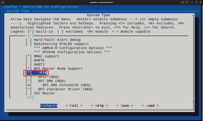
$ make menuconfigEnter inside "System Type --->" and select "SPI Master Mode Support" and "SPI0"
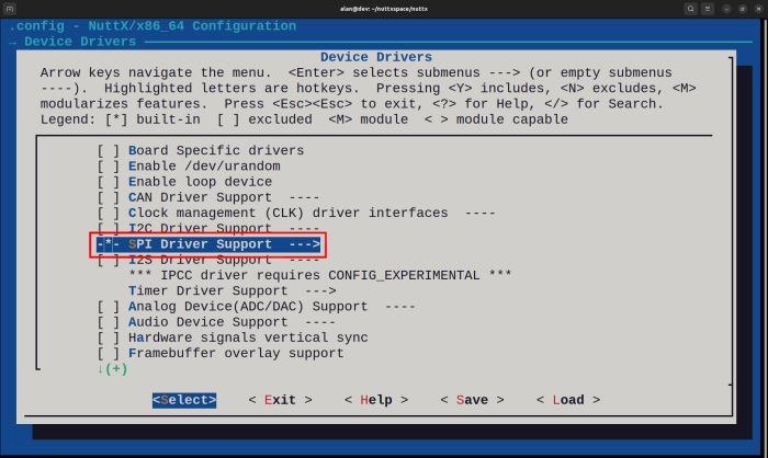
You can "Exit" from "System Type" and enter inside "Device Drivers --->", as you can see "SPI Driver Support" is automatically selected (pay attention at "-*-" in front of it, instead of "[*]")
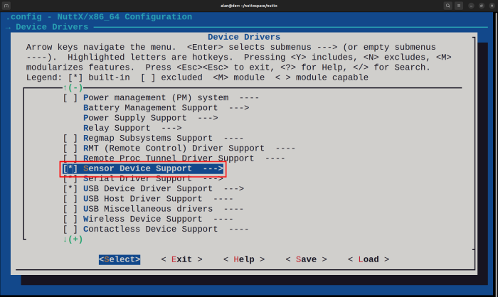
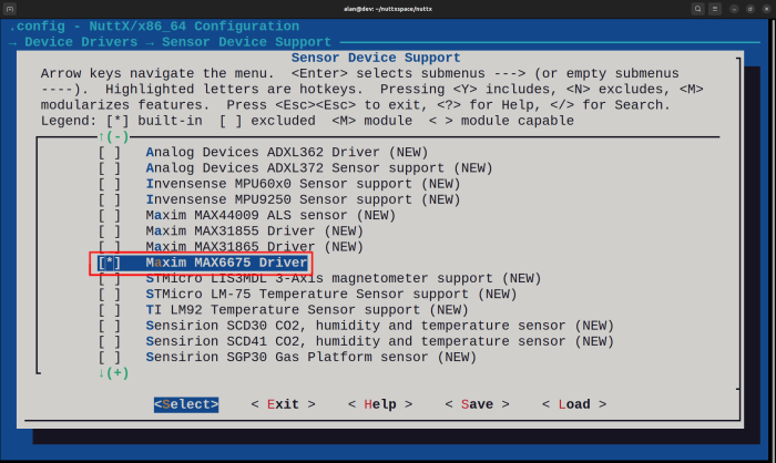
Press ENTER to enter inside "[*] Sensor Device Support --->" and select Maxim MAX6675 sensor:
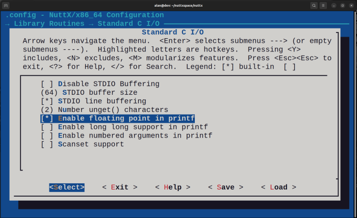
You can "Exit" from "Sensor Device Support" and from "Device Driver" and move down to enter inside "Library Routines --->" and once you are there enter inside "Standard C I/O --->" and select "[*] Enable floating point in printf" :
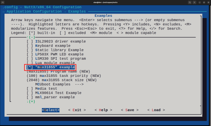
Finally "Exit" from "Standard C I/O --->" and "Library Routines --->" and move down to enter inside "Application Configuration --->", "Examples --->" and select the max31855 example test application:
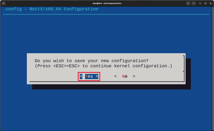
That is all! You can "Exit" from "Examples --->", "Application Configuration --->" and Exit and Save from menuconfig:
Add your PICO SDK PATH environment variable:
$ export PICO_SDK_PATH=/home/alan/pico-sdk
At this point we can compile:
$ make -j
You will see these lines at the end:
LD: nuttx
Generating: nuttx.uf2
tools/rp2040/elf2uf2 nuttx nuttx.uf2;
Done.
As you did in previous article, press and hold the Raspberry Pi Pico
BOOTSEL button and connect the USB cable. A "RPI-RP2" virtual disk
should appear on your file manager, the copy nuttx.uf2 to it.
After the file is flash the green LED will turn on, you can also run "sudo dmesg" to confirm that USB CDC/ACM was detected correctly.
Run minicom (or your preferred terminal console tool) and press "Enter" three times to let the "NSH>" appears. If you type "help" or "?" you will see that "max31855" application appears:
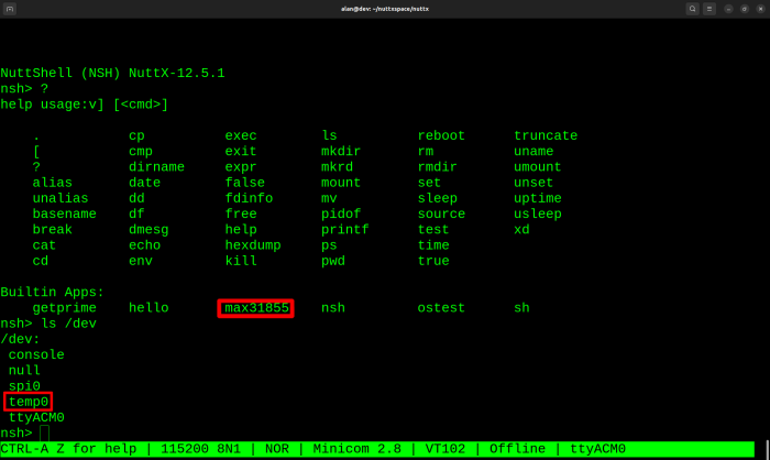
Also the "ls /dev" will reveal that the /dev/temp0 was created correctly.
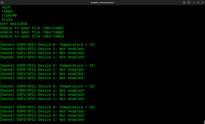
So if you run the max31855 application the temperature will be displayed:
That all folk!!! I hope you have enjoyed it.


- Comments
- Write a Comment Select to add a comment
To post reply to a comment, click on the 'reply' button attached to each comment. To post a new comment (not a reply to a comment) check out the 'Write a Comment' tab at the top of the comments.
Please login (on the right) if you already have an account on this platform.
Otherwise, please use this form to register (free) an join one of the largest online community for Electrical/Embedded/DSP/FPGA/ML engineers:


