


Arduino robotics #1 - motor control
Arduino Robotics
Beginner robotics is a series of article chronicling my first autonomous robot build, Clusterbot. This build is meant to be affordable, relatively easy and instructive. The total cost of the build is around $50.
1. Arduino robotics - motor control
2. Arduino robotics - chassis, locomotion and power
3. Arduino robotics - wiring, coding and a test run
4. Arduino robotics - HC-SR04 ultrasonic sensor
Meet Clusterbot!
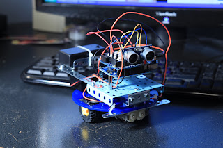
Meet Clusterbot, my first robot build. I like to let my projects name themselves, and by the time this robot was complete, he was such a cluster&*%# of jumperwires, zip-ties, velcro and erector-set parts that it was clear what his name should be. For all of Clusterbots deficiencies, it ended up being a terrific learning experience in mechanical design and motor control principles. This series of articles is also dedicated as a memorial to Clusterbot, who has since been dismantled and returned to various parts bins.
Today's post is going to focus on connecting and writing code for the Toshiba TB6612FNG motor driver.
Why do we need a motor driver? Can't we just connect the motors directly to the Arduino, just like an LED or any other component? Unfortunately, no. The output ports of a microcontroller are simply unable to handle the amount of current most motors will draw. The microcontroller used for this project was an Arduino Nano clone. The max current per pin on the Nano is 40 mA. The small toy motor used in Clusterbot can easily exceed this, pulling 500mA or more of current.
Mabuchi FA-130RA-18100 motors
The motors we are using for Clusterbot are the Mabuchi FA-130RA-18100 (see datasheet here). These are small and cheap toy motors. These little motors can pull anywhere between .1A and 2A (at stall). The current draw for my application is likely to be no more than .5A, but this is a rough guess.
Clusterbot won't cause the motors to reach their stall current, but it should be noted that the stall current rating of the motors is higher than max current rating for our motor controller. If stall current is a concern in your project, you will need to address it by installing some type of over-current protection, whether you use a fuse of some sort or a current sense feedback loop to the microcontroller. This topic is a little bit outside of the scope of this article, but I think it is worth mentioning.
The motor controller - Toshiba TB6612FNG
I chose the Toshiba TB6612FNG as the motor controller. Why? Mostly because it was cheap and easy to implement on a breadboard. Several companies sell The TB6612FNG on breakout boards, I went with the Pololu TB6612FNG Motor Driver Carrier. Only $4.95 and easy to use with a breadboard once you solder the included header pins to the carrier board.
Quick look at the specs of the TB6612FNG motor driver
- Two independent channels of bi-directional motor control
- Logic voltage range 2.7v-5.5v
- Motor voltage supply range 2.5V-13.5v
- Current output - 1A continuous, 3A maximum per channel. Can bridge channels to double output.
Wiring the TB6612FNG to your microcontroller, motor power source and motors

Left side
- GND - Microcontroller ground
- VCC - VCC from microcontroller (2.7V-5.5V)
- AO1 - Output to (-) lead of motor A
- AO2 - Output to (+) lead of motor A
- BO2 - Output to (+) lead of motor B
- BO1 - Output to (-) lead of motor B
- VMOT - positive pole of motor battery
- GND - negative pole of motor battery
Right side
- PWMA - PWM pin on microcontroller
- AIN2 - digital pin on microcontroller
- AIN1 - digital pin on microcontroller
- STBY - digital pin on microcontroller, or tie to VCC
- BIN1 - digital pin on microcontroller
- BIN2 - digital pin on microcontroller
- PWMB - PWM pin on microcontroller
- GND - GND of microcontroller
How do we control this thing?
First of all, nothing at all will happen if the STBY pin is not HIGH. Do this however you like, either in software by using another digital pin, or set it high permanently by tieing it directly to VCC.
If you want motor A to turn clockwise, set AIN1 to HIGH, AIN2 to LOW, PWMA to >0
If you want motor A to turn counter-clockwise, set AIN1 to LOW, AIN2 to HIGH, PWMA to >0
If you don't want to use PWM speed control of the motors, you can simply tie the PWMA and PWMB pins to VCC. In the case of an Arduino, this would be the equivalent of AnalogWrite(5,255);. Also concerning the PWM values - you will need to determine the minimum PWM duty cycle for the lowest speed you can run your motors at. Set a PWM value too low, and you can place the motor in a stall condition that will draw too much current. Low PWM values can also result in jerky operation.
In my particular case, a PWM value of 35 was necessary for the lowest speed smooth operation of my motors. This will be a function of your motor power source, motor size and the weight of your robot.
Now that you can control the direction and rate of spin of each motor, you can easily control your robot. In the case of Clusterbot, spinning motor A and B in the same direction at the same rate of speed will result in relatively straight travel in that direction. Spin the motors in opposite directions and you get a very quick zero-radius turn. You can experiment with different values for different types of sloping turns.
Due to a combination of poor chassis design and cheap toy motors, the output speed on each motor is a little different. You can compensate by altering the PWM duty cycle for one of the motors. For instance, you may find that you need to set motor A to 255 and motor B to 249 for straight line travel. A little experimentation may be necessary to calibrate.
Resources


- Comments
- Write a Comment Select to add a comment
Using an ESP32 would give more options - eg wireless control
To post reply to a comment, click on the 'reply' button attached to each comment. To post a new comment (not a reply to a comment) check out the 'Write a Comment' tab at the top of the comments.
Please login (on the right) if you already have an account on this platform.
Otherwise, please use this form to register (free) an join one of the largest online community for Electrical/Embedded/DSP/FPGA/ML engineers:


